Fuse Settings
| Fuse | Value | Remarks |
| BOD | 2.7V | You may want to disable BOD for low power applications. |
| OCDEN | ☐ | Not used. can be used for on chip debugging |
| JTAGEN | ☐ | This fuse is for JTAG debugging |
| SPIEN | ☐ | Enable Serial program and data downloading. This setting is required for using bootloader |
| WDTON | ☑ | Watchdog timer is on. |
| EESAVE | ☐ | Select to save EEPROM memory on chip erase |
| BOOTSZ | 4096 words | Bootloader size. set to 512 words if not using the bootloader |
| BOOTRST | ☑ | select to use the bootloader. |
| CKDIV8 | ☐ | Divide clock by 8 |
| CKOUT | ☐ | Not used. |
| SUT_CKSEL | 8 MHz, 16K CK + 65ms |
The microprocessor is shipped with internal RC oscillator and with the fuse CKDIV8 programmed resulting in 1 MHz clock. The startup time is set to maximum and timeout period enabled. So for reprogram fuse with or without yuktix bootloader following setting should be followed
Fuse register values
| Extended | HIGH | LOW | Remarks |
|---|---|---|---|
| 0xFD | 0xC8 | 0xFF | Default fuse settings for Yuktix PCB |
important
FUSE Register bits is
0 → programmed and 1 → not programmed.
Makefile for bootloader
        # MCU=
        # Processor frequency.
        #     This will define a symbol, F_CPU, in all source code files equal to the
        #     processor frequency. You can then use this symbol in your source code to
        #     calculate timings. Do NOT tack on a 'UL' at the end, this will be done
        #     automatically to create a 32-bit value in your source code.
        # ========================================
        #
        # rjha@yuktix.com
        # make changes for target here
        # BOOTLOADER_ADDRESS depends on BOOTSIZE inside source.
        # _______________
        # |___________|4K|
        #
        #
        # 2560V 0x3F000 (256kb - 4kb = 252kb = 252x1024 = 0x3F000)
        # 1284P 0x3F000 (128kb - 4kb = 124kb = 124x1024 = 0x1F000)
        #  640P 0x3F000 ( 64kb - 4kb =  60kb =  60x1024 = 0xF000)
        #
        #
        F_CPU = 8000000
        MCU = atmega1284p
        BOOTLOADER_ADDRESS = 0x1F000
        # =======================================


        # Bootloader
        # Output format. (can be srec, ihex, binary)
        FORMAT = ihex

        # Target file name (without extension).
        TARGET = stk500boot2
Compile bootloader for ATMEGA1284P
- Checkout arduino stk500 bootloader repo on your disk.
- cd to repo folder
- Change makefile to match architecture (atmega1284p) and F_CPU and bootloader address as shown above
- compile bootloader hex using makefile (default target, just type $make)
- This should create a stk500boot.hex file
- Burn the bootloader using ATMEL ICE on your PCB
Upload bootloader using ATMEL ICE
- Connect Atmel ICE to PCB ICSP pins (refer to PCB pinout diagram)
- Make sure ATMEL ICE connector is mating with ICSP header
- Download Atmel studio
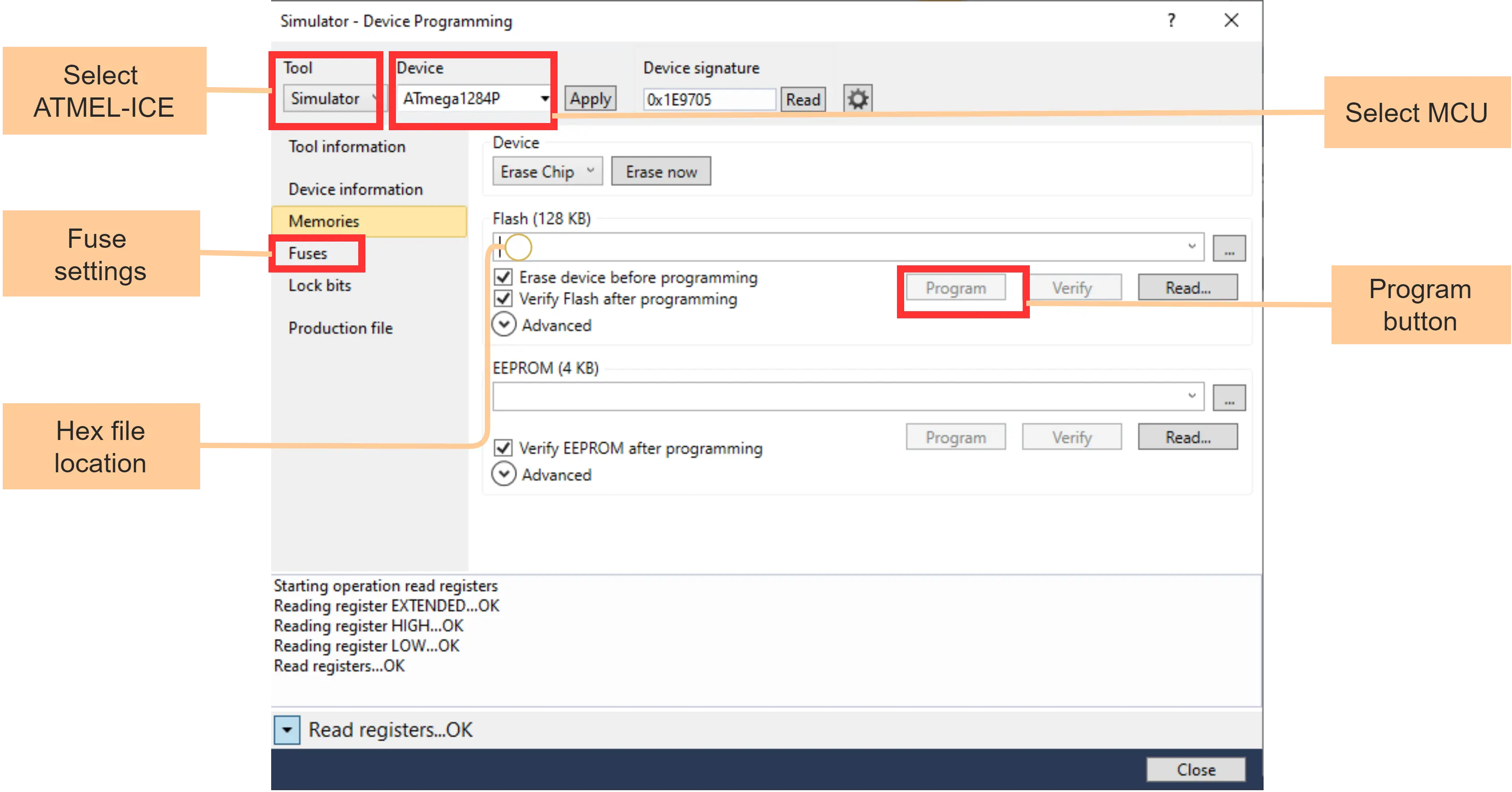
- Open Atmel studio and go to Tools → Device programming.

Now a screen will open where you can change the fuse settings and select the bootloader to be uploaded.
Upload hex files using bootloader
Use an in system programmer like AVRDUDE on your PC to upload application hex files with a bootloader. The bootloader should have been uploaded to the PCB using ATMEL ICE and BOOTRST FUSE setting should be enabled. You need to connect a serial cable to the DEBUG PORT (see the PCB pinout diagram) The connections are shown below for the FTDI RS232-TTL cable.
| Red | |
Vcc | NC | Do not connect |
| Orange | |
Tx | 1 | MCU Rx |
| Yellow | |
Rx | 2 | MCU Tx |
| Black | |
GND | 3,4 |
The command line for avrdude is show below. You can put this in your makefile.
$avrdude -C avrdude.conf -v -patmega1284p -cwiring -P /dev/tty.usb0 -b38400 -D -Uflash:w:$(hex file name).hex:i
Common Gotchas
- The Board is not powered ON
- ISP pins may not connected properly. check Vcc, MISO, MOSI, RST, Gnd, and SCK pins
- RESET pin may always be in pulled down state, triggering a RESET. check the RESET line.
- Select right MCU name
- Check ISP pin connections
- Board is not powered ON, turn ON the power.
- Reset button is not pressed before uploading the code.
- Check the cable connections for Rx, Tx and ground
- Check that you are using correct UART PORT.